torque converter for manual transmission

Torque Converter in Manual Transmissions⁚ An Overview

The concept of integrating a torque converter with a manual transmission is an intriguing idea, not commonly found in standard road cars. Unlike automatic transmissions, manual setups traditionally rely on a clutch. Exploring this combination raises questions about its practicality and potential benefits, including torque multiplication at low speeds.

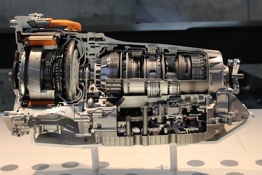
A torque converter is a fluid coupling device, primarily used in automatic transmissions, which allows the engine to spin independently of the transmission. It acts as a hydraulic clutch, transmitting power through fluid motion rather than a direct mechanical connection; This enables the vehicle to come to a stop without stalling the engine, unlike manual transmissions that require clutch engagement. Inside a torque converter, an impeller, driven by the engine, propels transmission fluid against a turbine, which is connected to the transmission input shaft. The resulting fluid pressure rotates the turbine, thereby transferring engine torque to the transmission.

A key characteristic of torque converters is their ability to multiply torque at lower engine speeds, effectively enhancing acceleration from a standstill. This is because the fluid within the torque converter provides some slippage at low speeds, allowing the impeller to spin faster than the turbine, thus increasing the force applied to the transmission. This capability is particularly valuable in automatic vehicles where smooth starts and effortless low-speed maneuverability are prioritized. The torque converter’s operation is dependent on the fluid dynamics within its housing, which can be complex and influence overall transmission performance.

How Torque Converters Function in Automatic Transmissions

In automatic transmissions, torque converters play a crucial role in facilitating smooth and seamless gear changes. They utilize a fluid coupling mechanism, consisting of an impeller, turbine, and stator, to transmit engine power to the transmission. The impeller, directly connected to the engine, rotates and propels transmission fluid towards the turbine, which is linked to the transmission’s input shaft. This fluid flow transfers the engine’s rotational energy to the turbine, causing it to rotate and drive the wheels.

The stator, positioned between the impeller and the turbine, redirects fluid flow to amplify torque at lower engine speeds. At higher speeds, the stator’s effect diminishes as the fluid flow becomes more direct. This fluid dynamic process allows the automatic transmission to engage the vehicle smoothly from a standstill and to shift gears without the need for a clutch pedal. The torque converter also provides a degree of slippage, which absorbs vibrations and shocks, contributing to a more comfortable ride. Its ability to multiply torque at lower speeds enables efficient acceleration and reduces the risk of stalling.

The Concept of Combining a Torque Converter with a Manual Transmission

The idea of integrating a torque converter into a manual transmission system is a departure from conventional automotive designs. Unlike traditional manual transmissions that rely on a mechanical clutch for engagement and disengagement, this concept introduces a fluid coupling element. In essence, the torque converter would be positioned between the engine and the manual gearbox, acting as a form of pre-transmission. The engine would initially drive the torque converter, which would then transmit power to the input shaft of the manual transmission.

The manual transmission would still retain its conventional gear selection mechanism, allowing the driver to choose specific gear ratios. However, the introduction of the torque converter aims to add a layer of smoothness and potentially enhance low-speed torque delivery. This setup would mean that even when the clutch is engaged in the manual transmission, the torque converter would already be in the process of sending power to the gearbox. This hybrid approach seeks to blend the efficiency and driver control of manual gearboxes with the fluid-based benefits of a torque converter.

Potential Benefits of a Torque Converter in Manual Transmissions

Integrating a torque converter into a manual transmission system could present several potential advantages. One key benefit lies in enhanced low-speed torque multiplication. The torque converter acts as a fluid coupling, multiplying the engine’s torque output at lower RPMs, which can translate to improved acceleration from a standstill and better pulling power in situations such as climbing steep inclines. This could reduce the need for frequent downshifting. Another advantage may be smoother starts and reduced driveline shock, the fluid coupling of the torque converter can absorb some of the impact of gear changes, making for a more comfortable and refined driving experience, particularly in stop-and-go traffic. Moreover, a torque converter could offer some level of protection against engine stalling.

The fluid coupling can also prevent the engine from stalling. By allowing some slip at low speeds, the torque converter could also make the vehicle more forgiving to driver error. This setup could potentially combine the best of both worlds⁚ the efficiency and control of a manual transmission with the smooth, torque-enhancing benefits of a torque converter.

Challenges and Problems with Torque Converter in Manual Transmissions

Integrating a torque converter into a manual transmission presents several significant challenges and potential problems. One primary concern is the loss of direct mechanical connection. Unlike a traditional manual transmission where engine power is transferred directly through a clutch, a torque converter utilizes fluid coupling, which inherently introduces some degree of slippage. This slippage can translate into reduced fuel efficiency compared to a standard manual gearbox. Another significant issue is the added complexity and weight. Torque converters are relatively bulky and intricate components. Adding this to a manual transmission can increase the vehicle’s overall weight, which can negatively impact handling and fuel consumption. Furthermore, the torque converter’s design might require alterations to the manual transmission’s shifting mechanism to accommodate the fluid coupling, potentially complicating the shifting process.

The torque converter also has a ‘stall speed’ below which it does not deliver significant torque, and that creates problems when a driver attempts to shift to neutral. This could lead to issues with traditional gear changes, as the converter does not offer a full disengagement of the drive like a clutch. Moreover, the added complexity can also increase maintenance costs and reduce reliability.

Torque Multiplication at Low Speeds

One of the most compelling advantages of a torque converter, particularly when considering its integration with a manual transmission, is its ability to multiply torque output at low engine speeds. This is a crucial feature that traditional manual transmissions lack. When an engine is running at low RPMs, it typically produces less torque. A torque converter addresses this limitation by using a fluid coupling to amplify the available torque. In essence, this means that an engine that produces a specific amount of torque at the flywheel can output a significantly higher amount at the transmission input shaft, especially at lower speeds. This can lead to greatly improved initial acceleration from a standstill, as well as enhanced pulling power at low speeds, making it easier to overcome inertia.

This attribute can be particularly beneficial in situations such as off-roading or when hauling heavy loads. The torque converter enables a vehicle to operate more efficiently at low speeds, making the vehicle more responsive and easier to control. Furthermore, this torque multiplication effect can make the vehicle more forgiving during start-ups, reducing the chance of stalling the engine, making the driving experience smoother and more refined.

Impact on Shifting

The integration of a torque converter with a manual transmission has a significant impact on the shifting process, creating a unique blend of automatic and manual characteristics. Unlike traditional manual transmissions that rely on a clutch for gear changes, the presence of a torque converter introduces a fluid coupling that can affect the smoothness of shifts. Specifically, the torque converter’s inherent slippage can lead to a smoother, less abrupt shift than a conventional manual transmission, especially during gear changes at lower speeds, reducing shock to the driveline. However, it is important to consider that this slippage means that the torque converter does not provide the direct, immediate engagement one would find with a manual clutch.

This can lead to a slightly different driving feel. Furthermore, the torque converter’s fluid coupling can result in some power loss during shifts, which may affect the overall efficiency compared to a purely manual system. The added complexity of managing the torque converter’s fluid dynamics could also mean that shifting might not be as direct or immediate as it is in a traditional manual set-up where the driver is entirely in control of the clutch. This is an important consideration for drivers accustomed to the direct feedback of a standard manual transmission.

Weight and Complexity Considerations

Introducing a torque converter into a manual transmission system significantly impacts the overall weight and complexity of the vehicle’s drivetrain. A torque converter itself adds considerable mass due to its intricate design, involving impellers, turbines, and stator components encased within a fluid-filled housing. This increase in weight can negatively affect a vehicle’s performance, potentially diminishing acceleration and handling capabilities, especially in smaller cars where weight is a critical factor. The integration also introduces a more intricate mechanical arrangement, with additional components like fluid pumps and control systems that need to work in harmony with the manual gearbox. This added complexity could make the system less reliable and more expensive to maintain compared to a standard manual transmission.

Moreover, the physical space requirements of a torque converter can pose design challenges, potentially requiring modifications to the vehicle’s chassis. The added intricacy of the system also leads to a more complex manufacturing process and potentially higher overall costs, making this combination a costly alternative compared to conventional manual gearboxes, which are known for their relative simplicity and low cost. Therefore, the trade-offs between the potential benefits and the increased weight and complexity need careful evaluation.

Comparison with Other Transmission Types⁚ AMT, CVT, DCT

When considering a manual transmission augmented with a torque converter, it’s essential to compare it with other modern transmission options like Automated Manual Transmissions (AMT), Continuously Variable Transmissions (CVT), and Dual-Clutch Transmissions (DCT). AMTs, which are essentially manual gearboxes with automated clutch and shifting mechanisms, offer a cost-effective alternative to traditional automatics, but they often lack the smoothness of a torque converter system. CVTs, known for their seamless acceleration, utilize belts and pulleys rather than gears, providing excellent fuel efficiency but sometimes lacking the direct feel of a geared transmission.

DCTs, on the other hand, employ two clutches to enable faster and smoother gear changes compared to AMTs and torque converter automatics, offering a sporty driving experience. A manual transmission with a torque converter would sit in a unique niche, potentially offering the driver engagement of a manual with the added benefit of low-speed torque multiplication and smoother starts, though at the cost of increased complexity. While AMTs are budget-friendly and CVTs focus on efficiency, DCTs prioritize performance, a manual with a torque converter would aim to bridge the gap between the manual and automatic driving experience, possibly appealing to a niche market.

Reliability and Maintenance of Torque Converters

Torque converters are generally regarded as reliable components within automatic transmissions, known for their robust design and longevity. When considering their application in a manual transmission setup, their reliability remains a key factor. Typically, torque converters require minimal maintenance, primarily involving regular transmission fluid changes to ensure proper lubrication and heat dissipation. The fluid is crucial for the torque converter’s operation, transferring power through hydrodynamic forces. Neglecting fluid changes can lead to overheating, reduced performance, and premature wear, as well as damage to the seals and internal components.

Unlike some other transmission types, such as CVTs which rely on belts and pulleys that can wear out, torque converters boast fewer moving parts which may mean less need for replacements. However, the added complexity of integrating a torque converter into a manual transmission might introduce new areas of concern regarding reliability, especially in the context of additional stresses and load during manual shifting. Therefore, a combined system would require careful engineering and potentially more frequent fluid checks to ensure the longevity and proper function of both the torque converter and the manual gearbox.

Applications Beyond Standard Road Cars

While the concept of combining a torque converter with a manual transmission isn’t common in standard passenger vehicles, there are potential applications for this technology in specialized areas. One such area is in high-performance off-road vehicles, where the torque multiplication of a converter at low speeds could provide enhanced crawling capabilities. This would allow drivers to navigate challenging terrains with greater control and reduced risk of stalling the engine, while still retaining the engagement and control of a manual transmission. Another potential application is in motorsports, particularly in drag racing or other high-torque applications.

The ability of a torque converter to smooth out power delivery and reduce shock loads on the drivetrain could be highly beneficial, improving acceleration and potentially reducing wear on other powertrain components. Furthermore, the combined setup could be used in heavy-duty industrial vehicles, where having both the low-speed torque multiplication of a torque converter and the direct gear engagement of a manual could be advantageous. In these scenarios, the advantages could outweigh the added complexity, making it a valuable choice.

Feasibility and Practicality

The feasibility of integrating a torque converter with a manual transmission is technically achievable, as demonstrated by some niche applications. However, the practicality for widespread use in standard road vehicles remains debatable. While the combination offers potential benefits such as enhanced low-speed torque and smoother power delivery, the added complexity, weight, and cost are significant factors. The increased weight of the combined setup could negatively impact fuel efficiency, which is often a priority for most car manufacturers and consumers. Moreover, the design and control system required to manage the torque converter in conjunction with a manual gearbox would be more complex than a standard system.

The increased manufacturing cost would also be a factor, especially compared to more conventional automatic or dual-clutch transmissions, making the concept less appealing for mainstream car production. Despite the theoretical advantages, the challenges in engineering, cost, and market acceptance make the combination unlikely to see widespread adoption in regular vehicles. The focus for most manufacturers is on improving the efficiency and speed of existing transmission technology, such as dual-clutch or traditional automatics, rather than combining the two different worlds.

coleman powermate 5000 manual pdf

Coleman Powermate 5000 Manual PDF⁚ An Overview

The Coleman Powermate 5000 generator is designed for reliable, portable power when utility power isn’t available. The manual provides essential information for safe operation, maintenance, and troubleshooting. It’s crucial for understanding the generator’s features, specifications, and warranty details to ensure optimal performance and longevity.

Identifying Your Coleman Powermate 5000 Model

Before seeking the correct manual, accurately identifying your Coleman Powermate 5000 model is crucial. Coleman Powermate produced a range of 5000-watt generators, each with slight variations in features, engine types, and control panel layouts. The model number is typically found on a sticker or nameplate affixed to the generator’s frame, often near the engine or control panel.

This label usually includes both the model number (e.g., PM0535000, PM0525302.03) and the serial number. Note these down precisely. The serial number can be helpful for warranty claims or when contacting customer support. Cross-referencing the model number with online resources or the Coleman Powermate website can further confirm you have the correct identification. Pay attention to any suffixes or revisions noted on the label (e.g., “.04” or “ER”), as these indicate specific versions requiring distinct manuals.

Using the wrong manual can lead to incorrect maintenance procedures, improper operation, or ordering incompatible replacement parts. Taking the time to correctly identify your model saves time and prevents potential damage.

Finding the Correct Manual PDF Online

Once you’ve identified your Coleman Powermate 5000 model, the next step is locating the correct manual in PDF format. Start by visiting the official Coleman Powermate website, if available, and navigate to their support or manuals section. Enter your model number in their search bar to check if the manual is directly downloadable.

If the official website doesn’t have it, try searching online using search engines like Google, DuckDuckGo, or Bing. Use specific search terms like “Coleman Powermate [Your Model Number] manual PDF” (e.g., “Coleman Powermate PM0535000 manual PDF”). Be cautious of unofficial websites offering manuals, as they may contain incorrect or incomplete information. Look for reputable websites specializing in manuals or equipment documentation.

Websites like ManualsLib, Electric Generators Direct, or even online forums dedicated to generators can be valuable resources. Before downloading, verify the manual matches your exact model number and revision. Preview a few pages of the PDF to ensure it covers the features and specifications relevant to your generator. Also, check the file size and scan the downloaded file with antivirus software to ensure it is safe.

Downloading the Powermate 5000 Manual PDF

After locating the correct Coleman Powermate 5000 manual PDF, the downloading process is usually straightforward. Most websites will have a clear download button or link, often labeled as “Download PDF,” “Get Manual,” or a similar call to action. Before clicking, make sure you’re on a secure website (look for “https” in the address bar) to protect your device from potential malware.

Once you click the download link, your browser will typically prompt you to choose a location to save the file; Select a folder on your computer or device where you can easily find it later, such as your “Downloads” folder or a dedicated “Manuals” folder. If the website opens the PDF directly in your browser, you can usually save it by clicking the “Download” icon within the PDF viewer or by using the “File” > “Save As” option in your browser menu.

Be patient while the file downloads, especially if it’s a large document. Once the download is complete, it’s a good practice to scan the file with your antivirus software to ensure it’s free of viruses or malware before opening it. After scanning, you can open the PDF using a PDF reader like Adobe Acrobat Reader or any other PDF viewer installed on your device.

Understanding the Manual’s Contents

The Coleman Powermate 5000 manual contains crucial sections. These detail safety, operation, maintenance, and troubleshooting. Understanding these ensures safe, efficient use and extends the generator’s life. Consult the manual before operating the generator.

Safety Precautions

Prioritize safety when operating a Coleman Powermate 5000 generator. The manual outlines critical precautions to prevent injury or damage. Always operate the generator in a well-ventilated area to avoid carbon monoxide poisoning. Never operate it indoors or in enclosed spaces. Keep children and pets away from the generator during operation and refueling. Before refueling, always turn off the generator and allow it to cool down completely.

Use only approved fuel containers and avoid spilling fuel. If fuel spills, clean it up immediately and allow vapors to dissipate before starting the generator. Inspect the generator regularly for any signs of damage or leaks. Never operate a damaged generator. Use appropriate grounding to prevent electrical shock.

Do not overload the generator beyond its rated capacity. Be aware of the risks of electrical hazards and use appropriate safety gear, such as gloves and eye protection; Store the generator in a safe, dry place when not in use, following all storage guidelines. Always consult the manual for specific safety instructions related to your model.

Operating Instructions

The Coleman Powermate 5000 manual provides detailed operating instructions to ensure safe and efficient use. Before starting, familiarize yourself with the generator’s controls and features. Check the oil level and add oil if necessary, using the recommended type. Ensure the generator is placed on a level surface. Connect the spark plug wire.

Fill the fuel tank with fresh, unleaded gasoline. Open the fuel valve and set the choke lever to the appropriate position for starting. If equipped, turn the engine switch to the “ON” position; Start the generator by pulling the recoil starter or using the electric start, if available. Allow the engine to warm up before applying a load.

Connect appliances or tools to the generator’s outlets, ensuring that the total load does not exceed the generator’s rated capacity. Monitor the generator’s performance and shut it down if any issues arise. When finished, turn off the generator, close the fuel valve, and disconnect any connected devices. Refer to the manual for specific instructions related to your model.

Maintenance Schedules

The Coleman Powermate 5000 manual provides crucial maintenance schedules to prolong the generator’s life and ensure optimal performance. Regular maintenance is essential for preventing breakdowns and maintaining efficiency. After the first 25 hours of operation, change the engine oil using the recommended type and viscosity. Subsequently, change the oil every 50 hours or at least once a season, depending on usage.

Clean or replace the air filter every 100 hours of operation, or more frequently in dusty conditions. Inspect the spark plug regularly and replace it annually or after 300 hours of use. Check and clean the fuel filter and fuel tank periodically to prevent fuel system issues. Inspect the generator for loose bolts, damaged wiring, and other potential problems.

Lubricate moving parts as needed. Store the generator properly when not in use, following the manual’s instructions for fuel stabilization and protection from the elements. Adhering to these maintenance schedules will help keep your Coleman Powermate 5000 running smoothly for years.

Troubleshooting Using the Manual

The Coleman Powermate 5000 manual is an invaluable resource when troubleshooting issues with your generator. Before seeking professional help, consult the manual’s troubleshooting section to identify and resolve common problems. The manual typically includes a comprehensive list of symptoms, possible causes, and recommended solutions;

If the generator fails to start, check the fuel level, spark plug, and air filter. Verify that the choke is properly engaged and that the on/off switch is in the correct position. If the generator starts but produces no power, check the circuit breakers and ensure that the connected devices are not overloading the generator.

For engine-related problems, consult the manual for guidance on checking the oil level, fuel lines, and carburetor. If the engine is running rough, inspect the spark plug and air filter. If the problem persists, the manual may recommend specific tests or adjustments. Remember to always disconnect the generator from the power source before performing any troubleshooting steps. The manual’s detailed diagrams and instructions can help you diagnose and fix many common issues, saving you time and money.

Finding Replacement Parts Information in the Manual

The Coleman Powermate 5000 manual is essential when identifying and ordering replacement parts for your generator. The manual contains detailed parts lists, exploded diagrams, and component breakdowns that help you pinpoint the exact part you need. These diagrams typically illustrate how each part fits within the generator’s overall assembly, making identification easier.

The parts list will provide part names, numbers, and brief descriptions. When ordering, use the part number to ensure you get the correct replacement. The manual may also include information on where to purchase parts, such as authorized Coleman Powermate service centers or online retailers.

It’s crucial to use the correct replacement parts to maintain your generator’s performance, safety, and warranty coverage. Using non-OEM parts could void the warranty and potentially damage the unit. The manual also includes safety precautions related to parts replacement, such as disconnecting the generator from power sources and wearing appropriate safety gear. Always refer to the manual before replacing any parts.

Warranty Information and Service Contacts

The Coleman Powermate 5000 manual is a vital resource for understanding your generator’s warranty coverage and how to access service and support. The warranty section outlines the terms and conditions, including the duration of coverage, what is covered (defects in material and workmanship), and what is not (normal wear, accidental damage, commercial use).

The manual will specify how to initiate a warranty claim, typically requiring proof of purchase and a description of the issue. It’s crucial to follow the outlined procedures to ensure your claim is processed correctly.

The manual also provides contact information for Coleman Powermate service centers and customer support. This may include a toll-free number, email address, or website. The manual may contain a list of authorized service centers in your region. Keep this information handy if you encounter problems with your generator. Remember to have your model and serial number available when contacting customer service.

Coleman Powermate Service Centers

The Coleman Powermate Service Centers play a crucial role in maintaining the optimal performance and longevity of your Coleman Powermate 5000 generator. These service centers are authorized to provide warranty repairs, routine maintenance, and comprehensive troubleshooting assistance. Finding a nearby service center is essential for prompt and reliable support when needed.

The generator’s manual typically includes information on locating authorized service centers. You can often find a service center by calling the toll-free number provided in the manual or visiting the Coleman Powermate website. The website usually has a search tool that allows you to find service centers based on your location.

These service centers are staffed with trained technicians familiar with Coleman Powermate generators. They have the expertise and equipment to diagnose and repair any issues you may encounter. Utilizing an authorized service center ensures that your generator receives quality service and that any warranty repairs are handled correctly, preserving your warranty coverage.

Alternative Resources for Manuals and Support

Besides the official Coleman Powermate website and service centers, several alternative resources can provide manuals and support for your Coleman Powermate 5000 generator. Online forums and communities dedicated to generators or power equipment often have users who can offer advice, troubleshooting tips, and even share scanned copies of manuals.

Websites specializing in manuals and documentation may also host the Coleman Powermate 5000 manual in PDF format. Online retailers that sell generator parts often have manuals available for download as a service to their customers. It’s crucial to verify the source’s credibility before downloading any files to avoid malware or incorrect information.
YouTube and other video-sharing platforms can be valuable resources for visual learners. Many users upload videos demonstrating maintenance procedures, troubleshooting steps, and repair techniques for generators like the Coleman Powermate 5000.

diaper genie manual

Diaper Genie Manual⁚ A Comprehensive Guide

Welcome to your comprehensive Diaper Genie guide! This manual will help you master every aspect of your diaper disposal system. From setup to troubleshooting, learn to keep your nursery fresh and odor-free with ease.

The Diaper Genie system offers a convenient and hygienic solution for diaper disposal. These systems are designed to lock in odors and simplify the process of discarding soiled diapers. The Diaper Genie utilizes a unique refill system with multi-layer bags that seal each diaper individually, preventing unpleasant smells from escaping into your nursery. Understanding how the Diaper Genie works, from loading refills to emptying the pail, is key to maintaining a fresh and clean environment for your baby; This guide is designed to provide you with all the necessary information.

Understanding Your Diaper Genie Model

To effectively use your Diaper Genie, it’s crucial to identify your specific model. Each model has unique features and components. Understanding these differences ensures proper use and maintenance for optimal performance.

Identifying Your Specific Model (e.g., Elite, Complete, Signature)

The first step in maximizing your Diaper Genie’s effectiveness is identifying its specific model. Common models include the Elite, Complete, and Signature versions; Each model has distinct features and slightly different operational nuances. Check the product packaging or the base of the unit for the model name. Knowing your model helps ensure you follow the correct instructions for assembly, refill replacement, and troubleshooting. Refer to the corresponding sections in this manual for model-specific guidance to maintain optimal performance and odor control.

Key Features and Components

Understanding the key features and components of your Diaper Genie is crucial for its proper use and maintenance. Essential components include the pail body, lid (often with an Air-Tite clamp), refill cartridge compartment, and the refill film itself. Some models may feature a foot pedal for hands-free operation or a carbon filter for enhanced odor control. The Air-Tite clamp is designed to seal odors inside the pail. Familiarize yourself with each part to ensure correct assembly, loading of refills, and effective diaper disposal. Knowing these features will optimize odor control and the lifespan of your system.

Initial Setup and Assembly

Get ready to use your Diaper Genie! This section guides you through unboxing, inventorying parts, and providing step-by-step assembly instructions. A proper setup ensures optimal performance and odor control from day one.

Unboxing and Parts Inventory

Carefully unpack your Diaper Genie and lay out all components on a clean surface. Cross-reference the included parts with the inventory list in this manual to ensure everything is present. Typical parts include the pail body, lid, clamp mechanism, refill cartridge (or starter refill), and potentially a carbon filter. Identifying all pieces beforehand streamlines the assembly process. Check for any signs of damage during shipping, and contact customer support if necessary.

Step-by-Step Assembly Instructions

Begin by attaching the clamp mechanism to the pail body, ensuring it clicks securely into place; Next, insert the refill cartridge into the designated compartment, following the arrows for correct orientation. If your model has a carbon filter, install it now. Test the lid’s opening and closing mechanism. Finally, pull out approximately 18 inches of the refill film and tie a knot at the bottom to create the initial bag. Verify smooth operation before use.

Using the Diaper Genie

Ready to dispose of diapers? This section guides you through loading refills and mastering the proper disposal technique. Ensure odor-free ease with every diaper change using these simple steps.

Loading a New Refill

Before you can effectively use your Diaper Genie, a new refill must be properly loaded. Start by removing the plastic seal from the new refill cartridge. Next, pull out approximately 18 inches of the film, enough to cover the bottom of the pail. Securely place the refill cartridge into the designated space within the Diaper Genie. Ensure the film is correctly positioned for optimal sealing. Close the lid and test the mechanism to confirm proper function. The Diaper Genie is now ready for use, effectively containing odors.

Proper Diaper Disposal Technique

To ensure optimal odor control, the proper diaper disposal technique is essential. Begin by opening the lid of your Diaper Genie. Fold the used diaper tightly, using the adhesive tabs to secure it and prevent tearing. Push the folded diaper through the clamp system until it is fully enclosed within the bag. Release the lid, allowing the sealing mechanism to engage. This action effectively locks in odors and keeps your nursery fresh. Regularly using this technique maximizes the effectiveness of your Diaper Genie system.

Emptying the Diaper Genie

Emptying your Diaper Genie is crucial for maintaining freshness. Knowing when and how to properly remove and tie off the bag ensures optimal odor control and easy waste disposal.

When to Empty the Pail

Knowing when to empty your Diaper Genie is essential for maintaining a fresh and odor-free nursery. A key indicator is resistance when pushing a soiled diaper through the clamp. This signals that the pail is nearing its capacity. Emptying frequently helps prevent unpleasant smells. An almost-empty indicator on the refill film may serve as an indicator. Regular emptying contributes significantly to overall room freshness. Don’t wait until it’s overflowing; a proactive approach is best!

How to Remove and Tie Off the Bag

Removing and tying off the bag in your Diaper Genie is a simple yet crucial step. Begin by pushing the designated button to access the full bag within the pail. Use the thing on the right to cut the bag. Next, carefully pull the bag upwards and out of the unit. Ensure you have enough slack to tie a secure knot at the top, sealing in odors. Dispose of the tied bag responsibly.

Refill Replacement

Running low on refills? This section guides you through identifying the correct refill type and installing a new cartridge. Keep your Diaper Genie ready for action with these simple steps.

Identifying the Correct Refill Type

Selecting the right refill is crucial for optimal performance. Different Diaper Genie models require specific refills, such as those for the Elite, Complete, or Signature pails. Using the wrong refill can lead to improper sealing and odor leakage. Check your Diaper Genie model number and consult the product packaging or the Diaper Genie website to confirm compatibility. An indicator on the refill film will also show when it needs replacing.

Installing a New Refill Cartridge

Installing a new refill cartridge is a simple process. First, remove the empty cartridge from your Diaper Genie. Then, take the new refill and remove any packaging. Locate the start of the film and pull out approximately 18 inches. Tie a knot at the end of the film to create a bag. Place the refill cartridge into the designated space within the Diaper Genie, ensuring it clicks into place securely. Close the lid, and your Diaper Genie is ready for use.

Cleaning and Maintenance

Regular cleaning is essential for odor control. Wipe down your Diaper Genie frequently with appropriate cleaners. This helps to maintain a fresh and hygienic environment in your baby’s nursery.

Recommended Cleaning Products and Methods

To maintain a hygienic and odor-free Diaper Genie, regular cleaning is crucial. For effective cleaning, it is recommended to use disinfecting wipes or a mild soap solution. Ensure that you wipe down all surfaces, including the lid, clamp, and interior of the pail. Pay special attention to areas where residue might accumulate. Allow the pail to fully dry before replacing the refill. Routine cleaning, along with proper deodorizing techniques, will keep your nursery smelling fresh.

Deodorizing Techniques

Combatting odors in your Diaper Genie requires proactive deodorizing. Scented refill cartridges are a primary defense, but additional measures can enhance freshness. Consider using baking soda; sprinkle some at the bottom of the pail to absorb odors. Alternatively, charcoal filters can be placed inside to neutralize smells. Essential oil-infused cotton balls provide a pleasant aroma. Regularly cleaning the pail with disinfecting solutions also contributes to odor control. These combined techniques ensure a consistently fresh-smelling nursery, complementing the Diaper Genie’s odor-locking design.

Troubleshooting Common Issues

Encountering problems with your Diaper Genie? This section addresses frequent issues. Learn to resolve odor control failures, bag tearing, and refill jamming. Keep your diaper disposal system functioning smoothly and efficiently with these solutions.

Addressing Odor Control Problems

Persistent odors from your Diaper Genie can be frustrating. Ensure proper sealing by checking the Air-Tite clamp. Empty the pail frequently, especially after disposing of particularly soiled diapers. Try using disinfecting and deodorizing cleaners regularly, following product instructions carefully. Consider replacing the carbon filter, if applicable, as it absorbs odors. Verify that you are using genuine Diaper Genie refills, as they are designed for optimal odor control. Tightly roll diapers to prevent leaks and odors. Proper maintenance is key to a fresh nursery.

Resolving Bag Tearing or Jamming

Bag tearing or jamming in your Diaper Genie often stems from improper loading or overfilling. Avoid forcing diapers into the clamp system, as this can damage the refill film. Ensure that you are using the correct type of refill cartridge for your model. When the pail is full, empty it promptly to prevent excessive strain on the bag. Check for any obstructions or debris that may be causing the jamming. Tightly roll diapers with the adhesive tabs secured to the inside to prevent them from catching and tearing.

Diaper Genie Alternatives

Exploring diaper disposal beyond Diaper Genie? Consider Ubbi’s steel pail or Munchkin’s options. Weigh the pros and cons, including refill costs and odor control, to find the perfect fit for your needs.

Comparison with Other Diaper Pail Systems (Ubbi, Munchkin)

When considering diaper disposal systems, the Diaper Genie is a popular option, but alternatives like Ubbi and Munchkin offer different features. The Ubbi pail, known for its steel construction, eliminates the need for proprietary bags, while Munchkin pails often focus on odor control through self-sealing bags. Evaluate factors like material durability, refill costs (considering options like Glad Forceflex bags), odor-locking mechanisms (such as double air-tight clamps or carbon filters), and overall capacity to determine the best fit for your needs.

Pros and Cons of Different Disposal Methods

Choosing a diaper disposal method involves weighing the pros and cons of various systems; Diaper pails, like the Diaper Genie, offer convenience and odor control but require specific refill bags. Alternatives include using regular trash bags which are cost-effective, though may lack odor containment. Flushing soiled diapers is generally discouraged due to environmental and plumbing concerns. Consider your budget, environmental impact, frequency of diaper changes, and sensitivity to odors when selecting the most suitable disposal approach for your household.

Safety Precautions

Safety First! Always keep the Diaper Genie out of reach of children to prevent accidents. Ensure proper disposal of used refills to maintain a safe and hygienic environment for your family.

Preventing Child Access

To ensure the safety of your children, always position the Diaper Genie in a location inaccessible to them. The pail and its components, particularly the refill bags, can pose a hazard if mishandled. Regularly check the surrounding area for any loose parts or discarded materials that could attract a child’s attention. It is advisable to instruct older children about the potential dangers associated with the Diaper Genie and its contents. Supervise young children closely in areas where the Diaper Genie is present to prevent accidental injury or ingestion of materials.

Proper Disposal of Used Refills

When disposing of used Diaper Genie refills, take precautions to minimize environmental impact and prevent the spread of germs. Seal the full refill bag tightly before placing it in your outdoor trash receptacle. Consider double-bagging the refill to further contain odors and leakage. Check with your local waste management guidelines for specific instructions on disposing of plastic films or diaper waste. Washing your hands thoroughly after handling used refills is essential to maintain hygiene. Explore options for recycling the plastic cartridge if your community offers such programs.

samsung rs261mdrs user manual

The Samsung RS261MDRS is a side-by-side refrigerator model known for its features like spill-proof shelves‚ power freeze/cool options‚ and a compact icemaker. This appliance typically includes a user manual for guidance on operation and maintenance.

Overview of the Samsung RS261MDRS Model

The Samsung RS261MDRS refrigerator is a 26 cu. ft. side-by-side model‚ designed with user convenience and optimal food preservation in mind. It features four tempered glass spill-proof shelves‚ which aid in easy cleaning and prevent liquids from dripping onto lower shelves. The refrigerator includes power freeze and power cool options for rapid chilling‚ alongside LED lighting for enhanced visibility. A compact icemaker is built in‚ providing a convenient source of ice. Additionally‚ the RS261MDRS has a door alarm to alert users if the doors are left open‚ and an external ice/water dispenser for easy access. It also boasts a real stainless steel finish that adds a modern touch to any kitchen. This model is designed for efficient cooling and user-friendly operation‚ making it a reliable choice for households seeking a feature-rich refrigerator.

User Manual and Documentation

The Samsung RS261MDRS user manual provides essential guidance for operating and maintaining the refrigerator. It includes safety information‚ feature details‚ and troubleshooting tips for users.

Accessing the User Manual for Samsung RS261MDRS

The user manual for the Samsung RS261MDRS refrigerator is readily available for download online. Multiple sources offer the manual‚ often in PDF format‚ allowing users to access it on various devices. You can find it on the official Samsung website‚ where it’s frequently provided alongside product support information. Additionally‚ third-party websites specializing in appliance manuals also host copies. These manuals are essential for understanding the appliance’s features‚ troubleshooting potential issues‚ and ensuring proper use. The manual typically includes detailed instructions on setting up‚ operating‚ and maintaining the refrigerator‚ making it a valuable resource for all owners. Furthermore‚ some sites offer direct links or buttons to download the user manual for easier access and usage.

Availability of Manuals in Different Languages

While the primary user manual for the Samsung RS261MDRS is often available in English‚ the availability of manuals in other languages can vary. Typically‚ major appliance manufacturers like Samsung will provide manuals in languages relevant to the regions where the product is sold. However‚ for this specific model‚ the readily accessible manuals are predominantly in English. If you require a manual in a different language‚ it’s advisable to check the official Samsung website for your specific region. You may also find that third-party manual websites have translated versions‚ though these might not always be official. Contacting Samsung customer support directly may provide further information on language availability or potential translation options for the RS261MDRS user manual.

Troubleshooting Common Issues

Common problems with the Samsung RS261MDRS include frost buildup‚ evaporator fan issues‚ damper control malfunctions‚ and potential main control board defects; These issues can affect cooling performance.

Identifying and Resolving Frost Buildup on Evaporator Coils

Frost accumulation on the evaporator coils in your Samsung RS261MDRS refrigerator can hinder cooling efficiency. The defrost heater assembly should melt away frost periodically. If this assembly fails‚ excessive frost will accumulate‚ obstructing airflow. To identify this issue‚ check if the coils are visibly frosted over. If so‚ you need to inspect each component of the defrost system. This includes testing the defrost heater‚ defrost thermostat‚ and defrost sensor. A faulty component will prevent the system from working properly‚ leading to frost buildup. Correcting this problem ensures proper cooling and prevents further issues with your refrigerator. This will also help maintain efficient operation of the refrigerator.

Diagnosing Problems with the Evaporator Fan Motor

The evaporator fan motor in your Samsung RS261MDRS is crucial for circulating cold air within the freezer and refrigerator compartments. If this fan malfunctions‚ cooling will be inadequate. To diagnose problems‚ first try to turn the fan blade manually. If it doesn’t turn freely‚ the motor likely needs replacement. Additionally‚ unusual noises from the motor also indicate an issue and require replacement. If the motor isn’t running at all‚ use a multimeter to check its windings for continuity. Lack of continuity signifies a defective motor. Replacing the faulty evaporator fan motor is often necessary to restore proper cooling and ensure your fridge operates correctly. If the fan motor has issues‚ the fridge may not cool correctly.

Understanding and Troubleshooting the Damper Control Assembly

The damper control assembly in your Samsung RS261MDRS regulates the flow of cold air from the freezer into the refrigerator compartment. This component opens and closes to maintain the correct temperature. If the damper doesn’t open properly‚ insufficient cold air will reach the refrigerator‚ causing temperature issues. Therefore‚ check the damper control to ensure it’s not stuck closed or broken. A faulty damper can lead to uneven cooling between the freezer and fridge. If you suspect a damper problem‚ inspect it for physical damage or obstructions that might prevent it from operating correctly. A replacement may be needed if the damper is defective‚ impacting the fridge cooling efficiency.

Addressing Potential Issues with the Main Control Board

The main control board in the Samsung RS261MDRS refrigerator is responsible for managing various functions. While it’s less commonly the source of problems‚ a defective main control board can cause a range of issues. Before suspecting the control board‚ it’s crucial to test more frequently faulty components. If problems persist after checking other components‚ consider the main board. A faulty control board might lead to inconsistent cooling‚ ice maker malfunctions‚ or display problems. Replacement of this board should only be considered after exhausting other troubleshooting steps. Ensure the power is disconnected before any work on the control board.

Ice Maker Functionality and Issues

The Samsung RS261MDRS features a compact icemaker. An ‘OFF’ indicator illuminates when the ice maker isn’t operating. Issues may arise‚ requiring troubleshooting or a reset.

Ice Maker Operation and Indicators

The Samsung RS261MDRS refrigerator includes a built-in ice maker designed for convenient ice production. Typically‚ when the ice maker is functioning correctly‚ it will produce ice automatically‚ filling the designated ice bin. An important indicator to be aware of is the ‘OFF’ indicator light. This light turns on when the ice maker is not actively operating‚ signaling that the ice production process is paused or has been manually turned off. This indicator helps users quickly identify the ice maker’s operational status‚ and is often located near the ice maker controls. Understanding the meaning of this indicator is crucial for monitoring ice production and troubleshooting any potential issues. If the ice maker is not producing ice‚ check the indicator light.

Troubleshooting Ice Maker Malfunctions

If your Samsung RS261MDRS ice maker is not producing ice‚ several factors could be responsible. Firstly‚ ensure the ice maker is turned on and not in the ‘OFF’ state‚ indicated by the ‘OFF’ light. If the light is off‚ and the ice maker is still not working‚ check for any obstructions in the ice maker tray or dispenser chute. A frozen water line can also prevent ice production‚ so inspect the line for any blockage or ice buildup. Additionally‚ confirm that the water supply to the refrigerator is connected and functioning properly. Consider testing or resetting the ice maker using the test button. If problems persist after performing these steps‚ further diagnosis or professional assistance might be needed.

Resetting the Ice Maker

Resetting the ice maker on your Samsung RS261MDRS refrigerator can often resolve minor issues that might be preventing it from functioning correctly. To reset the ice maker‚ locate the test button‚ which is usually found on the ice maker unit itself. Press and hold this button for a few seconds; this will initiate a reset cycle. After pressing the button‚ observe the ice maker for any movement or sounds‚ indicating that the reset process has started. If the reset is successful‚ the ice maker should begin its normal cycle. If the ice maker continues to malfunction after the reset‚ there may be a need for more extensive troubleshooting or professional repair. Always consult the user manual for any manufacturer-specific instructions.

Maintenance and Care

Proper maintenance of your Samsung RS261MDRS includes setting correct temperatures and replacing filters regularly. These actions ensure optimal performance and longevity of your refrigerator‚ preventing potential issues;

Setting Temperatures for Optimal Performance

To ensure your Samsung RS261MDRS refrigerator operates efficiently and keeps your food fresh‚ setting the correct temperatures is crucial. The refrigerator compartment should ideally be maintained at around 40°F (4°C). You can adjust the temperature using the designated ‘Fridge’ button on the control panel. For the freezer compartment‚ a temperature of 0°F (-18°C) is generally recommended. Use the ‘Freezer’ button to adjust this setting. Pressing these buttons allows you to cycle through the available temperature options. Remember that frequent door openings or placing warm items inside can affect internal temperatures. Allow sufficient time for the temperature to stabilize after adjustments. It’s also important to monitor the temperature regularly to ensure it remains consistent‚ thus preventing food spoilage and maintaining optimal performance of the appliance.

Filter Replacement for Samsung RS261MDRS

Maintaining clean and fresh water is essential‚ and the Samsung RS261MDRS refrigerator utilizes a water filter for this purpose. Regular filter replacement ensures the removal of impurities and maintains optimal water quality. It’s generally recommended to replace the filter every six months‚ although this may vary depending on water usage and local water quality. The filter is typically located inside the refrigerator compartment‚ often in the upper right corner. When replacing‚ be sure to purchase the correct filter model‚ such as the Samsung DA29-00020B / HAF-CIN/EXP. To replace the filter‚ follow the instructions in the user manual‚ which usually involve a simple twist-and-lock mechanism. Always flush the new filter with water after installation to remove any air or loose particles before using the dispenser. Regular filter changes will extend the lifespan of the refrigerator’s water system.

Additional Features and Information

The Samsung RS261MDRS includes features such as door alignment and leveling to ensure proper operation. It also provides options for a factory reset‚ if needed‚ for troubleshooting purposes.

Door Alignment and Leveling

Proper door alignment and leveling are crucial for the Samsung RS261MDRS refrigerator to function efficiently. If the doors are not aligned correctly‚ it can lead to issues such as uneven cooling‚ difficulty in closing the doors‚ and potential energy wastage. The user manual provides instructions on how to adjust the refrigerator’s leveling legs to ensure the unit is stable and the doors are aligned properly. This process involves checking the levelness of the refrigerator using a level tool and adjusting the legs accordingly. Correct door alignment also helps in preventing air leaks and maintaining the desired temperature inside the refrigerator‚ thus preserving the freshness of the stored food items. Additionally‚ properly aligned doors ensure that the door seals make proper contact with the refrigerator body‚ further optimizing its performance and energy efficiency. If the doors are not aligning‚ you may need to repeat the handle fixing process‚ ensuring the handle locking tabs are correctly matched.

Factory Resetting the Refrigerator

Performing a factory reset on the Samsung RS261MDRS refrigerator can be a useful troubleshooting step to resolve persistent issues or restore the appliance to its original settings. The process usually involves accessing a specific menu within the refrigerator’s control panel‚ as detailed in the user manual. A factory reset will clear all user-defined settings‚ including temperature adjustments‚ custom ice maker settings‚ and any other personalized configurations; This action is different from a simple power cycle and aims to address software glitches that might be affecting the refrigerator’s performance. It’s important to note that a factory reset does not typically affect the physical condition or stored food items‚ but it will revert the refrigerator’s settings to their default factory state‚ requiring the user to reconfigure their desired settings. Before initiating a factory reset‚ it’s recommended to consult the user manual or Samsung’s support website for specific instructions applicable to the RS261MDRS model. Additionally‚ if your model has a Family Hub screen you may need to use a reset switch located in the top of the right door‚ or navigate through the settings menu.

t6 pro smart thermostat installation manual

T6 Pro Smart Thermostat⁚ Installation Overview

The Honeywell T6 Pro Smart Thermostat offers a streamlined installation process, designed for both ease and flexibility. It often requires a trained HVAC technician. This thermostat works with various HVAC systems. The included UWP mounting system is also part of installation.

Package Contents

The Honeywell T6 Pro Smart Thermostat package typically includes several key components necessary for a successful installation. Inside the box, you’ll find the T6 Pro Thermostat unit itself, which serves as the primary interface for controlling your home’s heating and cooling system. A UWP (Universal Wall Plate) mounting system is also included. Also a Honeywell Standard Installation Adapter (J-box adapter) is included.

In addition to the thermostat and mounting system, the package contains a decorative cover plate. Usually small; size 4-49/64 in x 4-49/64 in x 11/32 in (121 mm x 121 mm x 9 mm). This plate is optional and can be used to conceal any existing wall imperfections or to provide a more aesthetically pleasing appearance. To facilitate the mounting process, screws and wall anchors are provided, ensuring a secure and stable attachment to the wall.

The package also includes two AA batteries to power the thermostat, along with comprehensive installation instructions and a user guide. These documents offer step-by-step guidance on the installation process, wiring configurations, and thermostat operation. It is recommended to read the manual carefully before installation. Reviewing the contents ensures you have everything required before proceeding.

Optional Cover Plate Installation

The Honeywell T6 Pro Smart Thermostat offers an optional cover plate for enhanced aesthetics and functionality during installation. This cover plate serves to conceal any existing blemishes or openings on the wall where the old thermostat was previously mounted. It provides a clean and professional appearance, ensuring the new thermostat seamlessly integrates with your home decor.

Before beginning the installation, assess the wall surface. If there are any visible imperfections, such as screw holes, paint discrepancies, or uneven textures, the cover plate can effectively hide these flaws. The cover plate is designed for easy attachment, typically using screws and anchors. Align the cover plate with the mounting location and secure it to the wall, ensuring it is level and flush.

Once the cover plate is installed, the UWP (Universal Wall Plate) mounting system can be attached over it. This creates a stable base for the T6 Pro thermostat. The cover plate not only enhances the visual appeal but also provides an additional layer of support and protection for the wiring and connections behind the thermostat. By using the optional cover plate, you can achieve a neat and polished installation.

UWP Mounting System Installation

The UWP (Universal Wall Plate) mounting system is a crucial component of the Honeywell T6 Pro Smart Thermostat installation. This system provides a standardized and straightforward method for securing the thermostat to the wall, ensuring compatibility with various wiring configurations and wall surfaces. Before starting, ensure that the power to the HVAC system is turned off to prevent electrical shock.

Begin by pulling the door open and inserting the necessary wires through the wiring hole of the UWP. Position the UWP against the wall, aligning it with the desired location. Use a level to ensure the UWP is perfectly horizontal before marking the positions for the mounting screws. Drill holes at the marked positions, using a drill bit appropriate for the wall material. Lightly tap the supplied wall anchors into the drilled holes using a hammer.

Place the UWP over the wall anchors and insert the mounting screws. Tighten the screws until the UWP is firmly attached to the wall. The UWP should be securely mounted without any wobble or movement. Once the UWP is installed, you can proceed with connecting the wiring to the designated terminals. This UWP ensures a stable and reliable mounting base for the thermostat.

Wiring Terminal Designations

Understanding the wiring terminal designations on the Honeywell T6 Pro Smart Thermostat is crucial for a successful installation. Each terminal is labeled to indicate its specific function within the HVAC system. These designations ensure that the thermostat is correctly connected to the heating and cooling equipment, preventing damage and ensuring proper operation.

Common terminal designations include R (Power), C (Common Wire), W (Heat), Y (Cool), G (Fan), and potentially others depending on the system type. The R terminal connects to the power supply, while the C wire provides a stable power source. The W terminal activates the heating system, and the Y terminal controls the cooling system. The G terminal operates the fan, circulating air throughout the home.

For heat pump systems, additional terminals such as O/B (Reversing Valve) may be present. It is essential to consult the HVAC system’s wiring diagram and the thermostat’s installation manual to identify the correct terminal connections. Incorrect wiring can lead to system malfunctions or damage. Always double-check the wiring before powering on the thermostat to ensure proper and safe operation.

Wiring Conventional Systems

Wiring conventional systems involves connecting the T6 Pro to standard heating and cooling setups. This usually includes R, W, Y, G, and C terminals. Correct wiring ensures proper functioning of heating, cooling, and fan operations according to system design.

Forced Air and Hydronics

When wiring the T6 Pro Smart Thermostat for forced air systems, identify the wires connected to your old thermostat. Typically, you’ll find wires for heating (W), cooling (Y), fan (G), and power (R). Some systems may also have a common wire (C) for continuous power. Connect these wires to the corresponding terminals on the T6 Pro’s UWP mounting system, ensuring they are securely fastened.

For hydronic systems, which use hot water or steam, the wiring process is similar but may involve fewer wires. You might only have wires for heating (W) and power (R), and perhaps a common wire (C). Again, connect these to the appropriate terminals on the UWP. It’s crucial to consult the system’s documentation to confirm the correct wiring configuration, preventing damage to the thermostat or the HVAC system.

Always turn off the power at the breaker before beginning any wiring work. After wiring, double-check all connections to ensure they are secure and correctly placed before restoring power and proceeding with the thermostat setup.

Thermostat Mounting

Once the UWP (Universal Wall Plate) is securely installed and the wiring is properly connected, you’re ready to mount the T6 Pro Smart Thermostat. Begin by aligning the thermostat with the UWP, ensuring that the pins on the back of the thermostat match the corresponding slots on the UWP. Gently push the thermostat onto the UWP until it snaps firmly into place. You should hear a click, indicating a secure connection.

After mounting, visually inspect the thermostat to confirm it is flush against the wall and properly aligned. If it seems loose or wobbly, double-check that the UWP is securely mounted and that all wiring is correctly connected and not obstructing the thermostat. Once you are satisfied with the physical mounting, restore power to the thermostat at the breaker. The thermostat should power on automatically.

If the thermostat doesn’t power on, ensure that the batteries are correctly installed, and the power switch is on. With the thermostat now mounted and powered, you can proceed with the system operation settings to configure it according to your specific needs.

System Operation Settings

After mounting, configure settings to match your HVAC system. System operation settings allow you to customize heating, cooling, and fan. Use the thermostat’s menu to access and adjust these settings. This ensures optimal performance and energy efficiency.

Fan Operation Settings

Configuring the fan operation settings on your T6 Pro Smart Thermostat allows you to customize how the fan behaves within your HVAC system. You can choose between different modes, such as “Auto” and “On,” to manage airflow and comfort.

In “Auto” mode, the fan operates only when the heating or cooling system is active. This is the most energy-efficient setting, as the fan isn’t running continuously. It’s suitable for most households, ensuring that air is circulated only when needed to maintain the set temperature.

Alternatively, “On” mode keeps the fan running constantly, regardless of whether the heating or cooling system is active. This provides continuous air circulation, which can help to even out temperature differences between rooms and improve air quality by continuously filtering the air.

Consider your specific needs and preferences when selecting the appropriate fan operation setting. If energy efficiency is a primary concern, “Auto” mode is the recommended choice; If you prioritize consistent air circulation and improved air quality, “On” mode may be more suitable.

The T6 Pro Smart Thermostat makes it easy to adjust these settings, allowing you to optimize your home’s comfort and energy usage based on your individual requirements. Experiment with both modes to determine which works best for your situation.

Installer System Test

The Installer System Test is a crucial step in the T6 Pro Smart Thermostat installation process. It ensures that the thermostat is correctly connected to your HVAC system and that all components are functioning as expected. This test helps to identify and resolve any potential issues before the thermostat is put into regular use.

During the system test, the thermostat will cycle through various heating and cooling stages, activating the fan and other components to verify their operation. This allows the installer to confirm that the wiring is correct and that the thermostat is communicating properly with the HVAC equipment.

It is important to carefully observe the system’s response during the test, noting whether each component activates as expected and whether there are any unusual noises or behaviors. Any discrepancies should be investigated and corrected before proceeding.

The Installer System Test is typically accessed through the thermostat’s menu or settings, following the instructions provided in the installation manual. The test may include options for testing heating, cooling, and fan operation, as well as other system-specific functions.

By performing the Installer System Test, you can ensure that your T6 Pro Smart Thermostat is properly installed and configured, providing reliable and efficient control of your home’s heating and cooling system.

Troubleshooting

Even with careful installation, issues can arise with the T6 Pro Smart Thermostat. This troubleshooting section aims to address common problems, ensuring smooth operation.

Problem⁚ Thermostat not powering on. First, check the batteries, replace them with fresh ones. If using C-wire, ensure it’s properly connected. Verify power at the breaker box.

Problem⁚ Display is dim or unreadable. Adjust the display brightness in settings. If that doesn’t work, replace the batteries.

Problem⁚ Thermostat not connecting to Wi-Fi. Ensure your Wi-Fi network is working. Enter the correct password. Move the thermostat closer to the router.

Problem⁚ Incorrect temperature readings. Check the thermostat’s location, away from direct sunlight or drafts. Calibrate the temperature in the settings menu.

Problem⁚ HVAC system not responding. Double-check wiring connections. Verify the thermostat settings match your system type. Consult an HVAC professional if needed.

Problem⁚ System constantly running. Ensure the fan setting is set to “Auto.” Check for stuck buttons or malfunctioning components. Contact a qualified technician.

For further assistance, consult the Honeywell Home support website or call their customer care line. Remember to have your model number ready for faster support.

hunter node-100 manual pdf

The Hunter NODE-100 is a battery-operated controller designed for single-station irrigation. It offers convenient, standalone operation with a focus on simplicity and efficiency. It is a common choice for small irrigation systems.

Overview of the NODE-100 Controller

The NODE-100 controller is a battery-powered irrigation solution from Hunter, designed for single-zone applications. This controller is known for its ease of use and is ideal for areas without readily available AC power. The unit offers a straightforward programming interface, allowing users to set watering schedules efficiently. It utilizes a DC latching solenoid, which contributes to its energy-saving design. The NODE-100 is often used for residential and small commercial landscapes where only one zone requires automatic watering. It is a popular choice due to its compact size, durability, and the convenience of battery operation. The controller also features an LCD display for clear visibility of settings and programming information. It’s designed to be weatherproof for outdoor use, making it a reliable option for various environments. The NODE-100 supports manual watering options, giving users added flexibility.

Key Features of Hunter NODE-100

The Hunter NODE-100 boasts key features like battery operation, single-station control, a DC latching solenoid, and an LCD display for easy programming and operation, making it a practical choice.

Battery-Operated Functionality

The Hunter NODE-100’s battery-operated design provides exceptional flexibility and convenience, eliminating the need for mains power connections. This feature allows for easy installation in remote locations or areas where access to electricity is limited, making it a versatile solution for diverse landscape irrigation needs. The controller is designed to work efficiently on battery power, ensuring reliable operation over extended periods. This also simplifies the setup process, as it requires no wiring, further enhancing user convenience. The unit’s efficient power management also contributes to the longevity of the battery life, which reduces the need for frequent replacements. This battery operated functionality is ideal for small, independent irrigation systems. Additionally, this makes it an environmentally conscious choice, as it reduces energy consumption, especially when combined with the solar panel option.

Single-Station Operation

The Hunter NODE-100 is specifically engineered for single-station operation, making it an ideal choice for controlling a single irrigation zone or a small, isolated area. This focused design simplifies the setup and programming process, providing a straightforward solution for managing irrigation in a targeted manner. This feature allows for precise control over the specific area, ensuring that water is delivered only where and when it is needed, thus promoting efficient water usage. This single-station functionality is particularly useful for applications such as small gardens, individual planters, or remote landscape areas. The NODE-100 is the go-to option for those requiring a simple, reliable, and battery-operated controller for precise irrigation management. Its focused design ensures that users can easily manage the water usage for a single, specific irrigation zone without the complexities of multi-zone systems.

DC Latching Solenoid

The Hunter NODE-100 utilizes a DC latching solenoid, which is a critical component for its battery-operated functionality. This type of solenoid is designed to operate with a minimal power draw, allowing the controller to maintain its operation over extended periods using battery power. The DC latching mechanism means that the solenoid only consumes power during the brief moments when it is switching between open and closed states. This power-efficient design is essential for maximizing the battery life of the NODE-100, reducing the need for frequent battery replacements; This helps to make the controller highly suitable for locations where there is no readily available AC power source. This contributes to the overall reliability and convenience of the NODE-100 controller, ensuring consistent and reliable operation of the irrigation system. The DC latching solenoid is a very effective component.

LCD Display

The Hunter NODE-100 incorporates an LCD display to provide users with clear and intuitive access to the controller’s settings and programming information. This digital display allows users to easily view the current date, time, and other critical programming details. The LCD screen enhances the user experience by presenting the necessary information in a structured and readable format, ensuring that users can navigate the controller’s functions with ease. It simplifies the process of setting up watering schedules and making adjustments as needed. The display also provides visual feedback on the controller’s operation and battery status, allowing users to monitor the device’s performance. The LCD display makes the NODE-100 user-friendly, especially for those who may not be familiar with irrigation system controllers. It is easy to read and understand the information provided on the screen.

Programming the Hunter NODE-100

Programming the Hunter NODE-100 involves setting the date and time, manual watering, and scheduling start times. This ensures the irrigation system operates as needed.

Setting Date and Time

To begin programming the Hunter NODE-100, setting the correct date and time is crucial for accurate irrigation scheduling. The process involves using the controller’s central button to access the settings menu. Once in the menu, the left and right arrow buttons allow you to navigate between the different setting options, such as year, month, day, hour, and minute. The plus and minus buttons are then used to adjust the displayed values for each setting. This straightforward interface makes it easy to precisely configure the date and time, which is essential for the controller to execute watering schedules correctly. Proper setup ensures that your irrigation system activates at the desired times.

Manual Watering Options

The Hunter NODE-100 offers convenient manual watering options, allowing users to bypass programmed schedules when immediate irrigation is needed. This feature is particularly useful for spot watering or testing the system. To initiate manual watering, you will typically navigate through the controller’s menu using the central button. The interface will then provide options to activate the station for a specified duration. The plus and minus buttons are used to adjust the watering time, giving flexibility for short bursts or longer watering cycles. This manual override capability ensures that users maintain full control of their irrigation system, even outside of the automated settings. The manual watering option provides a user-friendly way to attend to specific irrigation needs.

Programming Start Times

The Hunter NODE-100 allows for precise control over irrigation schedules through its start time programming feature. The controller utilizes three independent programs⁚ A, B, and C. Each of these programs has the capacity to store up to four start times. This allows for multiple irrigation cycles throughout the day, which is beneficial for different types of plants or soil conditions. Programming start times involves navigating through the controller’s menu using the center button, and then using the left and right arrow buttons to cycle through the options. The plus and minus buttons are used to adjust the hour and minutes of each start time. Once set, the NODE-100 will automatically initiate watering cycles at the programmed times, providing a hands-off approach to irrigation. This feature ensures consistent watering.

Hunter NODE-100 Variations

The NODE-100 is available with or without a solenoid. Multi-zone options like NODE-200, 400, and 600 control 2, 4, or 6 solenoids, offering expanded irrigation capabilities.

Models with and without Solenoid

The Hunter NODE-100 controller is offered in configurations that cater to different installation needs, specifically regarding the inclusion of a solenoid. You can purchase the NODE-100 either with an integrated solenoid, which provides a complete, ready-to-install solution for controlling a single irrigation zone, or without a solenoid, allowing for more flexibility in integrating with existing valve setups. This variation provides users with the choice to use their preferred solenoid brand or utilize a solenoid they already have on hand. The model with the included solenoid is often preferred for new installations where a direct and straightforward setup is desired. Conversely, the model without the solenoid offers greater customization for those looking to integrate the controller into existing systems or replace only the control unit without being forced to swap out a working solenoid. This dual offering makes the NODE-100 a versatile controller to meet specific project requirements.

Multi-Zone NODE Controllers (NODE-200, 400, 600)

Beyond the single-station NODE-100, Hunter offers a range of multi-zone controllers within the NODE series, including the NODE-200, NODE-400, and NODE-600. These models are designed for managing larger irrigation systems with multiple zones. The NODE-200 controls up to two zones, the NODE-400 handles four zones, and the NODE-600 can manage six separate irrigation zones. Each of these controllers operates on the same battery-powered, standalone principle as the NODE-100, maintaining ease of installation and operation in areas without readily available power. These multi-zone models are particularly well-suited for residential or small commercial landscapes requiring more than one irrigation valve. They expand on the NODE platform by offering the same straightforward programming and reliable performance found in the single-station unit, but with increased capability. The controllers manage multiple DC latching solenoids simultaneously, all within a single, battery-operated unit.

Technical Specifications and Support

The NODE-100 is compatible with the Hunter Freeze-Clik sensor. Users can find downloadable manuals and instructions online, along with other resources for support.

Sensor Compatibility (Freeze-Clik)

The Hunter NODE-100 controller is designed with compatibility for the Freeze-Clik sensor, enhancing its functionality in varying weather conditions. This sensor allows the irrigation system to automatically pause watering when freezing temperatures are detected, preventing damage to plants and the system itself. The Freeze-Clik works by sensing the ambient temperature and interrupting the watering cycle. This integration of the sensor provides an efficient method for managing irrigation based on environmental factors. It ensures that water is not wasted on frozen grounds, which can also lead to unsafe conditions. The sensor seamlessly integrates with the NODE-100 to offer a complete and smart irrigation solution.

Downloadable Manuals and Instructions

Comprehensive manuals and instructions for the Hunter NODE-100 controller are readily available for download, providing users with detailed guidance on setup, programming, and troubleshooting. These downloadable resources come in PDF format, ensuring easy access and compatibility across various devices. The manuals cover a range of topics, from basic installation procedures to advanced programming features, including setting date and time, manual watering options, and programming start times. Users can access these manuals to gain a thorough understanding of the controller’s functionality, ensuring optimal use and performance. They provide step-by-step instructions and clear diagrams to facilitate ease of use. These are available on multiple online platforms.

Available Support Resources

For users seeking assistance with the Hunter NODE-100, a variety of support resources are available to ensure smooth operation and resolve any issues that may arise. These resources include online forums where users can share experiences, ask questions, and receive guidance from other users. Additionally, the manufacturer provides direct support channels, such as a dedicated customer service helpline and email support, for more personalized assistance. Comprehensive troubleshooting guides are often included in the downloadable manuals, addressing common problems and providing solutions. The Hunter website also features a support section with FAQs, video tutorials, and other helpful materials. This combination of community and manufacturer support ensures users have access to the help they need.

trane tr150 manual

Trane TR150 Manual Overview

This section offers a general look at the Trane TR150 manual, highlighting its purpose for users. It serves as a starting point for understanding the various documents available, including service and programming guides, all crucial for the proper use and maintenance of the TR150.

Available Manual Types

The Trane TR150 documentation includes several key manual types to support different aspects of the device. These include the Service Manual, which covers maintenance and repair procedures, the Programming Manual, detailing parameter adjustments and settings, and the Quick Manual, offering a concise guide for safe installation and commissioning. These resources are available in PDF format, providing easy access to essential information. Furthermore, there’s the Design Guide, which focuses on motor control system design, completing the suite of documents for comprehensive TR150 support. Each manual serves a distinct purpose, aiding in the effective operation and troubleshooting of the TR150.

Trane TR150 Service Manual

This manual provides detailed guidance for maintaining and repairing the Trane TR150. It is a crucial resource for technicians performing service on the device, containing essential procedures.

Content and Purpose

The Trane TR150 service manual is a comprehensive document designed for technicians and service personnel who are responsible for maintaining and repairing the TR150 drive. It includes detailed procedures for troubleshooting, component replacement, and preventive maintenance tasks. The manual’s primary purpose is to ensure the reliable and efficient operation of the TR150 by providing clear instructions and technical specifications. It covers a range of topics from basic system checks to complex repairs, offering a complete guide for servicing the drive. It also aims to reduce downtime by facilitating quick and effective fault resolution, thereby prolonging the lifespan of the equipment and ensuring smooth operation.

Troubleshooting Information

This section provides critical guidance for identifying and resolving issues with the Trane TR150. It includes a detailed breakdown of common faults and alarms, offering clear steps for diagnosis. Users will find help in interpreting error messages displayed on the LCP, enabling them to quickly pinpoint the cause of the problem. Furthermore, the troubleshooting section outlines procedures for exterior fault resolution and offers useful tips to help navigate the diagnostic process. This information is designed to minimize downtime by facilitating efficient problem-solving and ensuring that the TR150 operates smoothly, thus maintaining optimal performance. It is an essential resource for technicians dealing with drive malfunctions.

Trane TR150 Programming Manual

The Programming Manual for the Trane TR150 details how to adjust settings. It provides guidance on modifying parameters for optimal performance, also including procedures for initialization to factory defaults.

Parameter Settings and Adjustments

This section of the Trane TR150 Programming Manual delves into the specifics of configuring the drive to meet diverse operational needs. Users will find comprehensive instructions on how to navigate the parameter menus, locate specific settings, and adjust them accurately. This includes detailed explanations of each parameter’s function and its impact on the connected motor and system. Adjustments like motor voltage, speed control, and ramp rates are covered, providing a full picture of the VFD’s configurable aspects. It is vital to understand these settings for efficient and reliable operation. Incorrect settings can lead to suboptimal performance or even system damage. Therefore, careful attention to the manual’s guidelines is crucial before making any changes.

Initialization to Default Settings

The Trane TR150 Programming Manual outlines clear procedures for restoring the VFD to its original factory settings. This process, often necessary when troubleshooting or starting fresh, ensures that all parameters are set to their default values. The manual details two primary methods for performing this reset, offering flexibility to users. This procedure is crucial for eliminating any custom configurations that may have caused operational issues. By returning to the baseline settings, users can begin with a known state, making troubleshooting easier and ensuring compatibility with the intended application. The process is outlined in an easy-to-follow manner, allowing users to quickly restore their drive to its original state without any confusion.

Trane TR150 Quick Manual

This manual provides essential information for safe installation and commissioning of the TR150. It is intended for use by qualified personnel who need a fast reference guide.

Safe Installation and Commissioning

The TR150 Quick Manual is crucial for ensuring safe installation and commissioning of the frequency converter. It emphasizes the importance of following all safety instructions and warnings. Qualified personnel should perform all installation and initial setup procedures. This manual guides users through the essential steps for safely connecting the device and preparing it for operation, paying particular attention to avoiding electrical hazards and preventing damage to the equipment. Proper grounding, correct wiring, and verifying voltage levels are key elements to consider. A thorough check should be completed after installation to confirm that the TR150 is functioning as expected.

TR150 and TR170 Design Guide

This guide provides essential information for designing motor control systems, specifically tailored for the TR150 and TR170 models. It assists in creating efficient and reliable HVAC systems, focusing on proper implementation.

Motor Control System Design

The design guide focuses on creating robust motor control systems using the TR150 and TR170 frequency converters. It details how to integrate these drives into various HVAC applications, ensuring efficient and reliable operation. Key considerations include selecting appropriate components, understanding variable torque mode, and optimizing control parameters for fans and pumps. Furthermore, the guide covers safety measures to prevent hazards during installation and operation. By following this guide, engineers can establish systems that maximize performance while minimizing energy consumption and ensuring longevity of the equipment. Proper design is essential for achieving the intended functionality.

Alarm and Warning Messages

This section details alarm and warning messages, crucial for identifying potential issues. A flashing display on the LCP indicates these conditions, providing number codes for troubleshooting and quick resolution of problems.

Identification and Interpretation

The Trane TR150 uses a flashing display on the Local Control Panel (LCP) to signal alarms or warnings. These alerts are accompanied by number codes on line 2 of the display, aiding in quick identification of the specific issue. Understanding these codes is vital for proper troubleshooting. Sometimes, a warning precedes an alarm, indicating an impending fault. It is essential to consult the relevant documentation for a detailed explanation of these codes and their corresponding corrective actions. These messages signal either existing faults or pending issues that require attention to ensure smooth operation. The user must be able to interpret them correctly to maintain the system efficiently.

Software and Firmware Updates

Software updates for the Trane TR150 can introduce new features, like variable speed cooling fans for longer life and reduced fan noise. These updates are regularly reviewed and should be installed.

Impact on Fan Noise and Life

The implementation of software version 4.0x and higher introduces variable speed cooling fans, significantly impacting both fan noise and the overall lifespan of the Trane TR150. This feature, designed to optimize performance in various operating conditions, aims to reduce noise levels under many scenarios. By adjusting the fan speed according to the actual cooling needs, the system operates more efficiently, thereby extending the fan’s life. This improvement is a key element in enhancing the reliability and user experience of the TR150, promoting quieter operations and reducing maintenance frequency.

Troubleshooting and Technical Support

This section provides guidance on addressing issues with the Trane TR150. It offers contact information for Trane technical support, emphasizing the importance of having equipment serial numbers readily available for assistance.

Contacting Trane Technical Support

For immediate assistance with your Trane TR150, contacting Trane technical support is a crucial step in resolving any complex issues that may arise. When reaching out, it is essential to have the equipment’s serial number readily available, as this will facilitate the support team in quickly accessing the necessary information regarding your specific unit. The provided contact number, 1-877-788-7263, connects you to Trane’s expert support team ready to assist with your technical inquiries. This direct line ensures efficient and focused troubleshooting, ultimately leading to quicker resolution of any problems you might encounter. Remember, having your serial number prepared helps expedite the support process.

Related Documents and Resources

This section provides links to the Trane e-Library and download section, offering further resources. These links provide access to additional documentation and tools for the Trane TR150.

Links to Trane e-Library and Downloads

Users can find a wealth of information and resources at the Trane e-Library, which is accessible through the iTrane portal. This platform provides a repository of documents, including manuals and guides, available for download in PDF format. These resources are crucial for maintenance, programming, and troubleshooting the Trane TR150. In addition to the e-library, the TraneDrives.com website offers additional software tools, such as the Trane Drive Energy Analysis Program, which allows users to compare energy consumption. Various PDF documents, including troubleshooting guides and parameter lists, are also available for download, supporting the efficient operation of the Trane TR150.

medela pump in style advanced breast pump manual

Medela Pump In Style Advanced⁚ An Overview

The Medela Pump In Style Advanced is a double electric breast pump designed for daily use by mothers. It features 2-Phase Expression technology, aiming to mimic a baby’s nursing pattern for efficient milk flow. This model was popular for its portability and convenience, often included with a discreet carrying bag.

The Medela Pump In Style Advanced is a double electric breast pump, designed to meet the needs of mothers who pump several times a day. It was created to offer hospital-grade performance in a compact, portable package, making it suitable for both home and work use. The pump incorporates Medela’s 2-Phase Expression technology, which is engineered to mimic the natural sucking rhythm of a nursing baby. This technology aims to maximize milk flow and provide a comfortable pumping experience for the user. The Medela Pump In Style Advanced was very popular and had been a choice of moms for over two decades. It came in various configurations, such as with a backpack or tote bag, to facilitate discreet and easy transport. While the original model with the backpack is no longer available, the core technology and design principles continue to influence Medela’s current breast pump models. This pump was designed for daily use and to provide an efficient and comfortable pumping experience for mothers.

Key Features of the Pump In Style Advanced

The Medela Pump In Style Advanced boasts several key features that made it a popular choice among breastfeeding mothers. Firstly, it utilizes 2-Phase Expression technology, which is designed to mimic the natural sucking pattern of a baby, resulting in more efficient and comfortable milk expression. The pump is a double electric model, allowing mothers to pump from both breasts simultaneously, saving time and increasing milk output. It also features adjustable speed and vacuum settings, enabling users to customize the pumping experience to their individual comfort levels. The pump is designed for daily use and intended to be portable, often coming with a convenient tote or backpack. The Pump In Style Advanced also included a battery pack, providing flexibility for pumping outside of the home or when access to an electrical outlet is limited; The dual-voltage capability of the pump allows for easy use while traveling internationally. These features collectively aimed to provide a reliable and efficient pumping solution for busy mothers.

Using the Medela Pump In Style Advanced

This section details the practical aspects of using the Medela Pump In Style Advanced. It covers assembly, cleaning, sanitization, and the actual operation of the breast pump. Instructions for both adapter and battery use are also provided.

Assembly of the Pump Kit

Before assembling the pump kit, ensure your hands are thoroughly washed to maintain hygiene. The process begins with gathering essential components, including the breast shield, breast shield connector, the white membrane, and yellow valve. It’s important to handle these parts carefully, avoiding contact with the inside of containers or lids to prevent contamination. Correct assembly is crucial for the pump’s optimal performance. Start by attaching the white membrane onto the yellow valve, ensuring they are properly aligned. Then, carefully fit the assembled valve and membrane onto the breast shield connector. Once this is done, securely connect the breast shield to the breast shield connector. Make sure all parts are correctly connected before proceeding. The faceplate and port cap should also be assembled following the user manual’s guide. This ensures the pump will have adequate vacuum and optimum performance. This methodical assembly process guarantees a secure and efficient pumping session.

Cleaning and Sanitizing the Pump Parts

Maintaining the cleanliness of your Medela Pump In Style Advanced parts is crucial for both your health and the pump’s performance. Before using the pump for the first time, all parts that come into contact with breast milk or your breasts must be cleaned and sanitized. After each use, immediately rinse all separated parts with clear, cool water to remove any milk residue. Then, thoroughly wash each part using warm, soapy water. A dedicated soap bottle, separate from dishes, is recommended to ensure hygiene. Allow all the cleaned parts to air dry completely in a clean area, and store them only when they are fully dry to prevent mold growth. It is essential to sanitize the pump kit parts once daily. While dishwashers can be used, note that food pigments may discolor parts. Tubing should never be placed in a micro-steam bag, but can be rinsed with clear water and air dried.

Daily Sanitization Procedures

Daily sanitization is a vital step in maintaining the hygiene of your Medela Pump In Style Advanced. It is recommended to sanitize the breast pump kit parts once every day, in addition to the regular cleaning after each use. To sanitize, you can use several methods, such as boiling the parts in water for a few minutes, or using a steam sterilizer. Ensure all parts are fully submerged in the boiling water or exposed to steam during sterilization. After sanitizing, allow the parts to air dry completely on a clean surface. Do not use a towel to dry them, as it may introduce germs. Proper drying is essential to prevent the growth of bacteria and mold. It’s important to note that the tubing should not be placed in a micro-steam bag. Always handle the sanitized parts with clean hands and store them in a clean, dry place until the next use.

Operating the Breast Pump

To operate the Medela Pump In Style Advanced, first ensure all parts are correctly assembled and the breast shields are properly positioned on your breasts. Connect the tubing to the breast shields and the pump. Then, plug the power adapter into an outlet, or use the battery pack. Turn on the pump, starting with the lowest vacuum setting and gradually increase the suction to a comfortable level. The pump features 2-Phase Expression technology, which begins with a rapid stimulation phase to initiate milk flow, followed by a slower, more powerful expression phase. You can adjust the vacuum and speed settings to find what feels best for you. Always ensure pumping is comfortable and stop if you experience pain. After your pumping session, switch off the pump and carefully disconnect the tubing from the breast shields. Remember to clean all parts that came into contact with breast milk immediately after use.

Powering the Pump⁚ Adaptor and Battery

The Medela Pump In Style Advanced offers two convenient power options⁚ an AC adapter and a battery pack. The included power adapter should be used with a standard electrical outlet, ensuring the pump is operated in an upright position. Always inspect the adapter and its cord for damage before use, and never pull the cord to unplug it. The battery pack, designed specifically for this pump, uses eight AA batteries, providing approximately two hours of pumping time. It’s essential to only use the Medela-approved battery pack to avoid any malfunctions or damage. When using batteries, make sure to insert them correctly. For those who travel, a portable vehicle adapter may be available, although compatibility should be checked against your vehicle’s manual. Remember that correct power usage is crucial for the pump’s performance and safety.

Maintenance and Troubleshooting

Proper maintenance and timely troubleshooting are essential for the optimal performance of your Medela Pump In Style Advanced. This section will guide you through identifying and resolving common issues, as well as keeping your pump and accessories in good working condition.

Troubleshooting Common Issues

If you encounter issues with your Medela Pump In Style Advanced, several factors could be at play. First, ensure all parts are assembled correctly, referring to the manual for proper setup. Check that the tubing is not kinked, twisted, or damaged, as this can affect suction. If the pump isn’t working, inspect the power adapter and battery pack for any damaged wires, discontinuing use if found. Make sure the faceplate and diaphragm are completely dry before reseating, ensuring a proper vacuum seal. If suction is weak, verify that the breast shield fits properly and that the white membrane and yellow valve are clean and intact. Should problems persist, consult the Medela Customer Service or the troubleshooting section in the manual for further assistance. If tubing becomes moldy, discontinue use and replace it immediately. It is also important to ensure the faceplate is seated correctly and snapped together at all connection points, ensuring optimal performance.

Maintaining the Pump and Accessories

Proper maintenance of your Medela Pump In Style Advanced and its accessories is crucial for its longevity and your safety. Regularly clean all parts that come into contact with breast milk after each use, using warm, soapy water, rinsing them thoroughly and allowing them to air dry completely. Sanitize the pump kit parts daily by boiling or using a microwave-safe steam bag, always following the manufacturer’s guidelines. Inspect the tubing for moisture and mold after each session; if mold is present, replace the tubing immediately. Clean the faceplate monthly. Also, do not store wet or damp parts as mold may develop. When cleaning the pump bag, use a damp cloth. For the power adapter, avoid wrapping the cord tightly around the plug. Store dry parts when not in use to prevent contamination. Properly maintaining your pump ensures optimal performance and minimizes the risk of issues during pumping sessions.

Additional Information

This section provides extra details such as PersonalFit breast shield sizing for comfort and optimal milk flow. It also covers proper breast milk storage guidelines when using the Medela Pump In Style Advanced, including using the cooler bag.

PersonalFit Breast Shield Sizing

Proper breast shield sizing is crucial for comfortable and effective pumping with the Medela Pump In Style Advanced. Medela’s PersonalFit system offers various sizes to accommodate different nipple diameters. A correctly sized breast shield ensures that the nipple moves freely within the tunnel, preventing discomfort and maximizing milk output. If the breast shield is too small, it can cause nipple pain and restrict milk flow. Conversely, if it’s too large, it can draw in too much areola tissue, also resulting in discomfort. Medela provides a guide to help mothers determine their optimal size, usually based on nipple diameter measurements. It’s recommended to check the fit regularly, as nipple size may change throughout the breastfeeding journey. Using the correct size improves pumping efficiency, milk supply, and overall experience.

Storing Breast Milk with the Pump In Style Advanced

The Medela Pump In Style Advanced often includes a cooler bag designed for storing expressed breast milk. This cooler bag typically requires a contoured ice pack to maintain a safe temperature for up to ten hours at room temperature. It’s designed to hold up to four 5 oz bottles of breast milk. When storing breast milk, it’s crucial to follow proper guidelines to ensure its safety and quality. Always use clean, sterilized containers, and label them with the date and time of expression. Freshly expressed milk can be stored at room temperature for a limited time, in the refrigerator for a few days, or frozen for longer periods. Ensure the cooler is securely closed during storage. Using the cooler bag correctly helps keep milk cool while traveling, making it convenient for mothers who are pumping on the go.

craftsman garage door opener manuals

Craftsman Garage Door Opener Manuals Overview

Craftsman garage door opener manuals are essential for safe and effective operation. These manuals provide detailed instructions for installation, programming, and troubleshooting. They also contain important safety information and warranty details, ensuring users operate the system correctly and safely, and that the system is within its warranty.

Finding Your Craftsman Model Manual

Locating the correct manual for your specific Craftsman garage door opener is crucial for proper usage and maintenance. The model number is typically found on a label located on the front panel of the opener unit. Once you have identified your model number, you can begin the search for the corresponding manual. Sears Parts Direct is a great resource for Craftsman manuals, offering a wide selection of downloadable PDF documents. You can also try searching online using your model number and “user manual” or “owner’s manual” as keywords. Numerous websites and online repositories may have the manual you need available for download. Be sure to verify the source of the manual to ensure its authenticity and accuracy. Checking the Craftsman website itself is also a good idea, as they will often have a library of manuals available. Always prioritize downloading from trusted sources to avoid any issues with outdated or incorrect information. With a little diligence, you’ll easily locate the perfect manual for your specific Craftsman opener.

Downloading Craftsman Manuals from Sears Parts Direct

Sears Parts Direct is a reliable source for downloading Craftsman garage door opener manuals. To begin, navigate to the Sears Parts Direct website and locate the search bar. Enter your specific Craftsman model number into the search field and press enter or click on the search button. The website will then display results related to your model, which may include parts, diagrams, and manuals. Look for the “manuals” or “owner’s manual” section and click to view available documents. The manuals are typically available as downloadable PDF files. Be sure to have a PDF reader installed on your device before proceeding. Once you have found the correct manual for your model, simply click the download button to save it to your computer or mobile device. Sears Parts Direct ensures that the manuals are accurate and up-to-date, providing a dependable source for all your Craftsman opener documentation needs. Always double check that you have the correct manual before using it.

Key Components in Craftsman Opener Manuals

Craftsman garage door opener manuals are structured to provide comprehensive information about the device. They typically include several key sections that are essential for understanding, installing, and maintaining your opener. One crucial component is the safety information, which details precautions to prevent accidents and injuries. Installation instructions offer step-by-step guidance, including diagrams and tool lists, ensuring proper setup. Programming instructions explain how to set up remote controls and wall buttons. The troubleshooting section provides solutions to common problems, such as a door not opening or closing correctly. Maintenance guidelines outline periodic checks and care to ensure the longevity of the opener. Finally, warranty details outline the terms of coverage and how to obtain service. These key components are designed to assist users in all aspects of operating a Craftsman garage door opener safely and efficiently. The manuals are very detailed.

Specific Craftsman Models and Manuals

Craftsman offers a variety of garage door opener models, each with its specific manual. These manuals provide detailed instructions and information tailored to each model’s unique features, ensuring proper use, maintenance, and troubleshooting for each particular opener system.

Craftsman 13953918D Manual Information

The Craftsman 13953918D garage door opener manual is a crucial resource for owners of this particular model. This manual provides comprehensive guidance on all aspects of the opener, including installation procedures, safety guidelines, and programming instructions. Users will find detailed diagrams and step-by-step instructions that help with proper setup and maintenance. The manual also covers essential troubleshooting steps, enabling users to address common issues effectively. It includes information on warranty terms and conditions, ensuring users are aware of their coverage. Furthermore, the manual details the use of accessories and safety features. Downloading this manual from Sears Parts Direct will help you to understand the nuances of this specific garage door opener. The document also highlights important safety precautions, which are necessary for preventing accidents and ensuring the door operates correctly. In addition, it provides information about parts replacement, allowing users to maintain their opener properly. By referring to this manual, owners can optimize the performance and extend the lifespan of their Craftsman 13953918D garage door opener.

Craftsman CMXEOCG471 Manual Details

The Craftsman CMXEOCG471 garage door opener manual offers detailed insights into the operation and maintenance of this model. This manual is essential for programming, troubleshooting, and understanding the various features of the opener. It covers key aspects such as how to program the travel limits, set up remote controls, and utilize the safety features. The manual also includes important troubleshooting steps for common issues, allowing users to address problems quickly and efficiently. Users will find clear instructions and diagrams that guide them through each procedure. The CMXEOCG471 manual provides specifics on the opener’s capabilities, including compatibility with different door types and its power output. It also highlights warranty information, ensuring users understand the terms of their coverage. In addition, the manual explains how to perform routine maintenance, which helps to prolong the lifespan of the opener. It includes sections on how to adjust settings, and other key functions to keep the system running smoothly. By consulting this manual, owners can ensure that their Craftsman CMXEOCG471 garage door opener operates reliably and safely. The manual also emphasizes safety protocols to avoid accidents.

Craftsman 139.18076 Series Manual Insights

The Craftsman 139.18076 series manual provides crucial information for several models within this line, including 139.18086, 139.18676, 139.18096, 139.18686, 139.18675, and 139;18696, and 139.18975. This manual is a comprehensive guide for operating, installing, and maintaining these 1/2 HP garage door openers designed for residential use. It includes detailed instructions for assembly, installation, and adjustment of the opener. The manual covers safety precautions, electrical requirements, and how to program remote controls. It also features sections on troubleshooting common issues, enabling users to resolve problems effectively. The insights provided help ensure that the opener functions smoothly and safely. The 139.18076 series manual explains the different components and how they work together, assisting users in understanding the mechanisms. It also includes maintenance schedules to prolong the life of the system. Furthermore, it offers information on warranty coverage and how to contact Sears for service or parts. The manual emphasizes the importance of following all safety instructions to prevent injuries. This document is an invaluable resource for anyone using a Craftsman 139.18076 series garage door opener, ensuring proper and reliable operation.

Using and Maintaining Your Craftsman Opener

Proper use and maintenance are crucial for your Craftsman opener. Regular checks, following the manual’s instructions, and addressing issues promptly will keep your system running smoothly. This section will guide you on programming, troubleshooting, and understanding safety information.

Programming and Troubleshooting Craftsman Openers

Craftsman garage door openers often require programming for remote controls and keypads, and the manuals provide step-by-step instructions on this process, detailing how to sync devices with the opener’s main unit. These instructions are essential for users to fully utilize the convenience features. Troubleshooting is also a key aspect covered in the manuals, and they often include common issues and their solutions, such as a door not responding to the remote, or the opener not closing properly. The manuals guide users through a systematic process to identify and resolve such problems, reducing the need for professional assistance. Additionally, safety features, like obstruction sensors, are addressed, with instructions on how to test and ensure they are working correctly. The manuals emphasize the importance of regular checks of these features, promoting safe operation of the garage door. Understanding these aspects is critical for the longevity and safe use of the opener.

Safety and Warranty Information in Manuals

Craftsman garage door opener manuals prioritize safety, providing crucial guidelines for safe operation and maintenance. These sections typically outline potential hazards and precautions to avoid accidents, especially during installation or repair. They emphasize the importance of testing safety features, like obstruction sensors, regularly to ensure they are functioning correctly. The manuals often include warnings regarding moving parts and the risks of improper use. Additionally, the manuals detail the terms and conditions of the warranty provided by Sears for the garage door openers, covering the duration of coverage and any limitations. This includes information on what types of repairs or replacements are covered under the warranty, and how to make a claim if needed. This warranty information is important for customers to understand their rights and how to obtain support if they encounter any issues with the opener during the warranty period. Following the safety instructions and being aware of the warranty terms will promote safe and secure use.

honeywell t6 install manual

Honeywell T6 Installation Overview

The Honeywell T6 Pro series offers both Wi-Fi and Z-Wave smart thermostat options. These devices are designed for easy setup using the Universal Wall Plate (UWP) mounting system. The T6 Pro supports features such as temperature control and fan operation. The T6 thermostats should not be placed near drafts, in direct sunlight or near heat sources.

Ring App Integration

The Honeywell Home T6 Pro Z-Wave Smart Thermostat seamlessly integrates with the Ring app, enhancing your home’s smart ecosystem. This integration allows users to control their thermostat directly from the Ring app interface, providing a unified platform for home management. You can adjust the temperature settings, switch between heating and cooling modes, and control the fan’s on/off status, all from your smartphone or tablet. The convenience of this integration means you can manage your home’s climate from anywhere, at any time. This feature is particularly useful for maintaining optimal comfort while saving energy. The Ring app integration streamlines thermostat control, making it more convenient and accessible. This enhances the user experience by providing a single app for security and climate controls. The integration simplifies home automation, allowing for synchronized control of various smart home devices. The process of integrating the T6 Pro with the Ring app is user-friendly.

UWP Mounting System

The Honeywell T6 thermostat utilizes a Universal Wall Plate (UWP) mounting system designed for easy and flexible installation. This system simplifies the mounting process and is suitable for various wall types. The UWP is included in the thermostat packaging and serves as the base to which the thermostat is attached. To begin, you’ll need to open the package to locate the UWP, which is a key component for proper installation. Once you have the UWP, position it on the wall where you intend to install the thermostat. It’s crucial to level the plate and mark the hole positions for screws. Ensure you drill the holes at the marked positions, using appropriate tools. The UWP’s design allows for easy wire management, ensuring secure and neat wiring. The UWP facilitates the secure attachment of the thermostat to the wall. The UWP system simplifies the installation process, making it accessible to a wide range of users.

Installation Steps

The installation of the Honeywell T6 involves several key steps. These include correctly wiring the thermostat and securely mounting the UWP to the wall. Following these steps correctly will ensure proper operation of the device.

Wiring the Thermostat

When wiring the Honeywell T6 thermostat, it is crucial to follow the terminal designations carefully. Begin by pulling the door open on the UWP, revealing the wiring access points. Insert the wires through the designated wiring hole located on the UWP. It’s important to ensure that each wire is connected to its corresponding terminal, matching the labels from your old thermostat or as outlined in the installation manual. To secure the wires, depress the terminal tabs and firmly insert the wire. Double-check that all connections are secure to prevent any loose wires or shorts. This step is fundamental for proper thermostat operation and prevents any potential damage. For ventilation systems, specific wiring configurations may be necessary, so consult the manual for accurate guidance. Proper wiring is essential for the thermostat to communicate effectively with the HVAC system and provide accurate temperature control. After wiring, make sure to arrange the wires neatly inside the UWP for a clean and secure installation.

Mounting the UWP

Begin the process of mounting the UWP by first opening the package to locate it. Carefully position the UWP on the wall, ensuring it is level before marking the desired hole positions. Next, using the marked locations, proceed to drill the holes. Insert wall anchors into the drilled holes, then carefully place the UWP over the wall anchors. Once the UWP is in place, insert the mounting screws and tighten them to secure the plate to the wall. Make sure the UWP is firmly attached to provide a stable base for the thermostat. This precise mounting is important for the stability and correct operation of the thermostat. Ensure the plate is not loose, and that it sits flush against the wall. This step-by-step approach will ensure a successful and secure installation of the UWP.

Advanced Setup

The Honeywell T6 offers advanced setup options through the Installer Setup (ISU) menu. Accessing this menu allows you to configure specific settings. The ISU provides various options to customize thermostat functionality. These settings can enhance the performance and efficiency of the system.

Installer Setup (ISU) Access

To access the Installer Setup (ISU) menu on your Honeywell T6 thermostat, you’ll need to follow a specific procedure. This menu is designed for advanced configuration and is not typically accessed during normal use. Begin by pressing and holding the “CENTER” button and the button simultaneously. Keep these buttons pressed for approximately three seconds. This action will initiate the advanced menu, which is a prerequisite for accessing the ISU. Once you have successfully entered the advanced menu, you will need to navigate further to reach the ISU settings. Typically, you’ll find that the “Select” button is the key to progressing into the ISU. By using the “Select” button, you can then enter the Installer Setup menu, which contains the advanced settings for your thermostat. These steps are crucial for accessing the deeper customization options available for your Honeywell T6.

ISU Navigation and Options

Once inside the Installer Setup (ISU) menu of your Honeywell T6 thermostat, navigating through the options is straightforward. You’ll primarily use the “Select” button to cycle through the different available menu settings. Each press of the “Select” button will advance you to the next option within the ISU. To make adjustments or selections within each menu item, you will use the buttons. These buttons will allow you to change the values or choose from the available options for each setting you navigate to. This system provides a user-friendly way to modify the advanced settings of the thermostat. The ISU offers various parameters that can be configured, and it is important to consult the manual for a complete understanding of each specific setting; Remember, Differential is NOT deadband.

Placement and Power

The T6 thermostat should be positioned away from drafts, direct sunlight, or heat sources, and at a height of 1.2 to 1.5 meters from the floor. The device uses AA batteries for primary or backup power.

Thermostat Location Guidelines

Proper placement of your Honeywell T6 thermostat is crucial for accurate temperature readings and efficient operation. Avoid installing the thermostat in areas that are exposed to direct sunlight, as this can cause the device to register a higher temperature than the actual room temperature. Similarly, locations near heat sources, such as radiators, fireplaces, or direct sunlight, should be avoided to prevent inaccurate readings. Drafty areas, such as near doorways, windows, or air vents, can also lead to inconsistent temperature measurements. The ideal location should have good air circulation and be representative of the average room temperature. It is recommended to install the thermostat at a height of 1.2 to 1.5 meters from the floor, a height which is typically at eye level for most adults which helps make the display easy to see and access. This height also ensures that the thermostat is positioned in the area of the room where the temperature is most consistent and most comfortable. Finally, make sure the chosen spot is easily accessible for any adjustments or maintenance that may be needed in the future.

Battery Installation

The Honeywell T6 thermostat can be powered by either your home’s existing wiring or by using batteries as a primary or backup power source, ensuring continuous operation during power outages. To install the batteries, you will need to access the battery compartment, typically located at the front or back of the thermostat. Remove the thermostat from the wall plate to locate the battery slots. The T6 thermostat uses AA batteries, and you will need to insert the correct number, usually two, into the designated slots, noting the correct polarity (+ and -) as indicated inside the compartment. Make sure the batteries are new or fully charged to ensure proper functionality. Once the batteries are correctly installed, securely reattach the thermostat to the wall plate. These batteries provide backup power, maintaining the thermostat’s settings and schedule in the event of a power outage. It is recommended to replace these batteries when they are low or every year to maintain reliability and operation. Proper battery installation ensures your thermostat continues to work reliably.

Additional Information

For added installation flexibility, an optional cover plate can be utilized. This is particularly helpful when mounting the thermostat over an electrical junction box. It can also be used to conceal any paint gaps left by the previous thermostat.

Optional Cover Plate Usage

The Honeywell T6 thermostat installation process includes the option to use a cover plate, which serves both practical and aesthetic purposes. This cover plate is not a mandatory component for the thermostat’s functionality; however, it provides a solution for specific mounting scenarios and can enhance the overall appearance of the installation. One of the main uses for the cover plate is when mounting the T6 thermostat directly over an existing electrical junction box. In such cases, the cover plate provides a neat and secure interface between the thermostat and the junction box, ensuring a proper installation. Furthermore, it is often the case that when replacing an old thermostat, the new one does not perfectly cover the previous mounting area. The cover plate, therefore, acts as a solution for hiding paint gaps or any marks left on the wall from the old thermostat, providing a clean and professional finish. This can be especially useful if the surrounding wall paint does not match the new thermostat’s color. The cover plate is designed to be easily installed, adding to the user-friendly nature of the entire Honeywell T6 installation process.